
Registers, counters and state transitions
A word of storage needs an update contract
A register groups stored bits into a word. Its useful definition includes width, reset value, write enable, update event and observation rules. A 64-bit register is not merely sixty-four unrelated bits: the surrounding circuit or instruction semantics determines when the word may change and which consumers can observe it. Register files add address selection and multiple access ports; architectural register names add a software-visible meaning over whatever physical storage implements them.
For a synchronous register with data D, enable E and present state Q, the ordinary next-state equation is Q_next = E ? D : Q. A multiplexer selects new data or feedback before the storage elements. If reset has priority, the equation becomes reset ? initial : (E ? D : Q). Reversing the priority changes behavior when reset and enable are asserted together. A schematic that omits this case leaves part of the machine unspecified.
An enable differs from a clock. In a clock-enable design the clock can continue toggling while the data selection retains Q. Proper clock gating suppresses clock activity through a cell designed to avoid spurious pulses. Replacing enable logic with an arbitrary combinational gate on the clock can create additional capture events. Software writing a C field models the intended transition but does not reproduce either physical circuit.
Register files and simultaneous access
A file of N registers of width w stores Nw data bits before considering decoding, port logic and protection. A selected read can be represented by a multiplexer over register words. A selected write combines an address decoder with per-register enable. Additional read or write ports increase interconnect and selection cost, often more significantly than adding a few storage bits. Exact area and delay depend on the cell organization.
Reading and writing the same address in one cycle requires an explicit rule: the read might return old data, new data through bypass, or an unspecified value under a forbidden collision. Two writes to the same register require priority or rejection. A processor pipeline cannot derive these rules merely from the phrase “register file.” Bypass networks and hazard detection enforce the chosen contract when instructions overlap.
Architectural names need not map permanently to physical cells. Register renaming can assign a new physical destination to each instruction while preserving the ISA's visible naming. A software emulator can instead store one current value per architectural register. These implementations may be functionally equivalent at the instruction boundary while differing radically in timing, power, speculative state and recovery machinery.
ChrisCPU's register representation
ChrisArchitectureState contains sixteen 64-bit general-purpose values with both indexed and named access through a union. The initial indices map RAX, RCX, RDX, RBX, RSP, RBP, RSI and RDI to zero through seven; the remaining names cover R8 through R15. RIP, RFLAGS, control registers, segment state and other architectural fields are stored separately. The structure also contains a TSC field and sixteen 16-byte XMM slots. A field's existence is not evidence that every associated instruction is implemented.
The union means gpr[4] and the named rsp refer to the same represented value rather than two copies requiring manual synchronization. The source declaration is the evidence for that relationship. It is not a stable serialized file format: compiler layout, alignment and the rest of the structure matter before raw bytes can cross an ABI boundary. A snapshot interchange format would need its own explicit contract.
chris_read_gpr and chris_write_gpr reject register indices outside zero through fifteen. They assume valid caller pointers and a supported operand-size context. Their width parameter is in bytes. Reads mask the requested portion. Writes implement different preservation rules depending on the operand width, which is why replacing every write with a whole-word assignment would be incorrect.
| Write size | Destination update | Preserved portion |
|---|---|---|
| 1 byte, ordinary low byte | Replace bits 7:0 | Bits 63:8 |
| 1 byte, legacy high byte | Replace bits 15:8 | Bits 63:16 and 7:0 |
| 2 bytes | Replace bits 15:0 | Bits 63:16 |
| 4 bytes | Assign masked 32-bit value | Upper 32 bits become zero |
| 8 bytes | Replace whole word | None |
The legacy high-byte selection applies when the decoded instruction has byte operand size, no REX prefix, and register encoding four through seven. The helper maps that encoding to indices zero through three and shifts by eight. With a REX prefix, those encodings select low bytes instead. This is an instruction-encoding rule expressed as a storage selection, not a different width of the underlying 64-bit register.
Starting with RAX = 0x1122334455667788, a low-byte write of 0xaa yields 0x11223344556677aa; a legacy high-byte write yields 0x112233445566aa88. A 16-bit write of 0xbbcc yields 0x112233445566bbcc. A 32-bit write of 0xaabbccdd yields 0x00000000aabbccdd. These cases distinguish preservation, shifting and zero extension without relying on the byte order of a host memory dump.
Deriving counters from addition and enable
An unsigned binary counter of width w implements Q_next = (Q + 1) mod 2^w when enabled. Bit zero toggles at every increment. Bit i toggles when all less-significant bits are one. Thus each next bit can be written as Q_i XOR the carry into that position. The counter is a specialized adder with one operand fixed, not a separate mathematical operation.
A ripple counter clocks one stage from another stage's output, so transitions propagate through several local events. A synchronous counter uses one clock and computes each bit's next input combinationally. Intermediate ripple patterns can confuse a decoder that observes the count without waiting for settling. Even synchronous outputs have skew, so asynchronous consumers still need a protocol. “Synchronous counter” does not establish coherent crossing into another clock domain.
A modulo-M counter for a non-power-of-two M can compare Q to M − 1 and select zero instead of Q + 1. The comparison and reset selection add logic to the next-state path. Values M through 2^w − 1 are unused encodings; the design must decide how they recover if reached. A saturating counter instead holds its maximum value. A wrapping count, a saturating statistic and a generation number serve different purposes even when their storage width is identical.
Ring position and sequence number are different objects
A ring of N slots often selects slot = sequence mod N. The slot repeats frequently, while the sequence carries additional progress information. If N is a power of two, masking with N − 1 gives the same nonnegative remainder, but the conceptual invariant remains modular indexing. Two equal slot numbers do not imply that producer and consumer are at the same logical position.
A finite-width sequence itself eventually wraps. For w-bit counters, unsigned difference (producer − consumer) mod 2^w equals the true outstanding distance only under an external bound preventing an entire modulus of unobserved progress. For ordering comparisons based on the sign of a modular difference, the stronger half-range restriction is typically required. These are different contracts. A queue whose capacity is far smaller than the modulus can enforce the distance bound through ownership and backpressure.
| Sixteen-bit sequence | Eight-slot position | Meaning |
|---|---|---|
| 65534 | 6 | Near sequence wrap |
| 65535 | 7 | Last representable sequence |
| 0 | 0 | Next event after wrap |
| 1 | 1 | Following event |
If the consumer has sequence 65534 and the producer has sequence 1, modular distance is three. Treating the producer as “behind” because its numerical value is smaller would be wrong. Conversely, an unconstrained producer could make 65536 advances and return to the same sequence; equality alone cannot detect that history. Counter arithmetic must therefore be explained together with capacity and ownership.
The concrete VirtIO queue counters
Virtq stores qsz, nfree, free_head and last_used as 16-bit quantities, along with software descriptor links. virtq_bytes accepts power-of-two sizes from two through VQ_MAX, which is 128 in the inspected header. Available and used indices reside in the shared byte buffer, separate from those software fields. The helper reads and writes their little-endian representations explicitly.
virtq_publish reads the available index, chooses idx % qsz, writes the descriptor head to that ring position and then publishes (uint16_t)(idx + 1). virtq_take compares the device-written used index with last_used; equality means no new completion. Otherwise it reads one entry at last_used % qsz, checks that its descriptor ID is within the queue, returns its ID and length, and advances last_used modulo 65536.
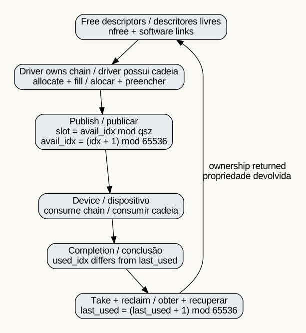
The publication sequence contains memory barriers around shared-memory publication; on x86 the local helper emits mfence, while its other branch is only a compiler barrier. This inspected implementation does not establish a portable DMA synchronization contract for every architecture. Nor does virtq_publish independently prove that a descriptor is allocated, unique or safe to reuse. Its bounds check is necessary but ownership remains a caller responsibility.
Allocation walks n descriptors and costs O(n); publishing one head and taking one completion have O(1) local work. Reclamation walks the software chain. The fixed arrays bound storage, but malformed ownership or repeated reclamation can still corrupt the logical free list. A numerical counter in range is not sufficient proof that every descriptor belongs to exactly one owner. The invariant connects free-list membership, device-visible chains and completion handling.
Instruction counts are another kind of counter
In cpu_run, cpu->steps, cpu->arch.tsc and the local count n are incremented after the execution path reaches the loop tail. Breakpoint, fetch failure and decode failure can leave earlier. Consequently, the count describes this backend's software progression rather than elapsed host cycles or a universal count of successfully retired physical instructions. A path that reaches the tail after setting a halt or exception status can still increment those values.
The run budget compares n with max_steps. This is a bound on loop progression within one call, not a wall-clock deadline. An expensive instruction or device operation can take more host time than a cheap one. A scheduler or benchmark must not translate the budget into seconds without an independently defined timing model. The same distinction separates a queue sequence, a clock frequency divider and a diagnostic event statistic.
State-machine interpretation and reset
A counter is a finite-state machine with a particularly regular transition function. A controller can combine it with phase state: idle, active, waiting or failed. Reset must restore a coherent tuple of phase, count, valid bits and ownership. Clearing only the count can accidentally make old entries look new. Clearing only a valid flag can strand allocated resources. Reset correctness is therefore a relation among fields, not a list of independent assignments.
For a register bank, simultaneous architectural updates must be described using old state and next state. For a queue, producer publication and consumer acknowledgment are separate transitions whose ordering establishes ownership transfer. For an emulator, a helper's partial-register update is one component of instruction execution. These mechanisms share the idea of state evolution while having different synchronization boundaries.
Evidence and limits
This chapter's implementation claims come from the declared source files at the recorded revision. The hexadecimal examples are direct applications of the masks and shifts in chris_write_gpr; the queue examples derive from the inspected 16-bit increments and modulo indexing. No physical register-file area, gate delay or queue throughput measurement is asserted. The arithmetic source probe validates the separate flags helper, not these register or queue interfaces.
The most consequential integration properties remain coherent instruction writeback, valid decoded widths, queue ownership across device access and reset behavior across the full machine lifecycle. They require their respective subsystem tests and architectural contracts. Registers and counters provide the vocabulary for stating those properties precisely; they do not make them automatic.