
PCI and PCI Express
Scope
PCI defines a discoverable hardware model, not merely a connector. A PCI function has configuration space, identifiers, class information, command/status control, address resources, capabilities and interrupt mechanisms. PCI Express preserves this software model while replacing the old shared parallel bus with a packet-switched serial fabric.
ChrisOS already relies on PCI for storage, networking, USB, audio and graphics. The current kernel can access legacy configuration space, identify functions by vendor/device or class, enable decoding and bus mastering, map BARs and follow standard capability chains used by modern VirtIO PCI devices.
The current implementation is still deliberately incomplete. ACPI MCFG is detected but not parsed into ECAM access; configuration offsets are only eight bits; there is no central topology-aware enumerator, recursive bridge traversal, MSI/MSI-X core, generic resource allocator or PCI root complex in ChrisVM.
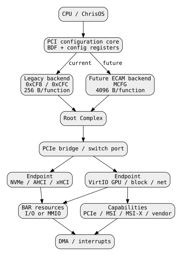
PCI versus PCI Express
Conventional PCI used a shared parallel bus. Devices shared electrical address, data and control lines and required arbitration for bus ownership.
PCI Express uses point-to-point serial links. Switches route packets between ports, root complexes and endpoints.
The lower layers changed radically, but the programming model intentionally retained:
- bus, device and function addressing;
- vendor and device IDs;
- class/subclass/programming-interface fields;
- configuration space;
- BARs;
- command/status registers;
- standard capabilities;
- interrupt configuration.
This compatibility is why a PCIe NVMe controller is still discovered as a PCI function.
PCIe protocol layers
PCIe can be understood through three primary layers.
| Layer | Main responsibility |
|---|---|
| Transaction | memory, configuration, I/O and message requests/completions |
| Data Link | link-local reliability, sequence numbers, CRC and replay |
| Physical | lanes, signaling, encoding and link training |
A CPU MMIO access does not cause ChrisOS to construct a packet manually. The root complex translates processor-side transactions into PCIe Transaction Layer Packets.
Root complex, switches, bridges and endpoints
The root complex connects CPU/memory to PCIe. Root ports lead into links. Switches fan one upstream path into downstream ports. Endpoints implement devices. Bridge semantics provide the software-visible routing structure between bus-number domains.
A correct OS enumerator therefore discovers a topology rather than a flat list.
BDF addressing
A conventional PCI function is selected by:
The tuple is usually written as BDF.
means bus 2, device 5, function 3.
One package can expose several functions. Drivers bind to functions, not to the physical package as an indivisible unit.
Configuration space
Every function provides configuration registers.
Important fields in a type-0 compatible header include:
| Offset | Meaning |
|---|---|
| 0x00 | Vendor ID and Device ID |
| 0x04 | Command and Status |
| 0x08 | Revision, Programming Interface, Subclass, Base Class |
| 0x0C | Header Type among other legacy fields |
| 0x10..0x24 | BAR0..BAR5 |
| 0x2C | Subsystem Vendor/Subsystem ID |
| 0x34 | standard capability pointer |
| 0x3C | Interrupt Line and Interrupt Pin |
Conventional PCI exposes 256 bytes per function. PCIe extends this to 4096 bytes while keeping the first 256 bytes compatible.
That distinction is immediately relevant to ChrisOS because pci_read and pci_write currently accept uint8_t offsets. They cannot reach 0x100..0xFFF.
Vendor and Device IDs
Offset 0x00 contains:
Vendor ID 0xFFFF conventionally means that no function responded.
ChrisOS uses this rule throughout probing.
Modern VirtIO devices use vendor 0x1AF4 and device-specific IDs. Vendor/device matching identifies a family precisely; class matching expresses a vendor-independent programming model.
Class, subclass and Programming Interface
Offset 0x08 contains:
ChrisOS currently recognizes examples such as:
| Tuple | Use |
|---|---|
| 01:06 | SATA/AHCI probe path |
| 01:08 | non-volatile memory/NVMe path |
| 04:01 | AC97/audio path |
| 0C:03:00 | UHCI USB |
| 0C:03:30 | xHCI USB |
Programming Interface is important because one subclass can contain more than one register programming model.
The current AHCI and NVMe probes primarily match class/subclass, while xHCI includes Programming Interface.
Header Type
The byte at offset 0x0E defines the header layout.
Low seven bits identify:
- type 0: ordinary endpoint;
- type 1: PCI-to-PCI bridge;
- type 2: CardBus bridge.
Bit 7 on function 0 indicates multifunction capability.
A generic enumerator should probe function 0, read Header Type and probe functions 1..7 only when appropriate. Type-1 bridges must lead enumeration into their secondary bus.
ChrisOS does not yet implement this central algorithm.
Legacy Configuration Mechanism #1
Current pci_read and pci_write form:
The address is written to port 0xCF8. The data dword is transferred through port 0xCFC.
Bit layout:
| Bits | Meaning |
|---|---|
| 31 | enable |
| 23:16 | bus |
| 15:11 | device |
| 10:8 | function |
| 7:2 | dword register |
| 1:0 | zero |
For BDF 02:05.3 and offset 0x14:
The chapter checker reproduces this value.
SMP race in CF8/CFC access
CF8/CFC is a shared address/data mechanism.
CPU0 can receive B's selected register.
The entire select-plus-data cycle must therefore be serialized when configuration access can occur concurrently.
Current pci_read/pci_write have no global PCI configuration lock. This is a real correctness limitation as ChrisOS evolves beyond single-threaded early boot.
Why Mechanism #1 is insufficient for PCIe
Mechanism #1 reaches only the conventional 256-byte space.
PCIe provides 4 KiB per function. Extended capabilities occupy offsets 0x100..0xFFF.
A kernel restricted to eight-bit offsets cannot generically implement PCIe extended facilities such as Advanced Error Reporting and many other extended capabilities.
The normal ACPI path is ECAM described by MCFG.
ECAM geometry
Enhanced Configuration Access Mechanism maps configuration space into memory.
For an MCFG allocation:
The strides follow from the layout:
one function = 0x1000 bytes
8 functions  = 0x8000 bytes per device
32 devices   = 0x100000 bytes per bus
The register field occupies 12 bits, giving 4 KiB per function.
ACPI MCFG in current ChrisOS
acpi_probe scans XSDT entries and recognizes signatures including APIC, MCFG and FACP.
For MCFG it currently reports the table's presence.
It does not parse MCFG allocation records, map ECAM windows or expose an ECAM configuration backend.
Therefore the accurate status is:
MCFG signature discovery: implemented
MCFG allocation parsing: not implemented
ECAM configuration access: not implemented
The acpi-platform chapter will cover ACPI table validation and allocation records in detail.
Segment groups
PCI systems can contain multiple segment groups.
A globally scalable identity is therefore:
A future ChrisOS PciAddress structure should carry segment even if initial support accepts only segment zero.
Enumeration is topology traversal
PCI bridges contain Primary, Secondary and Subordinate Bus Number fields.
A conceptual enumerator is:
enumerate_bus(bus):
    for device in 0..31:
        probe function 0
        if absent:
            continue

        visit function 0

        if multifunction:
            probe functions 1..7

visit function:
    record identity
    parse header
    parse BARs
    parse capabilities

    if type-1 bridge:
        enumerate secondary bus
This models the hardware graph rather than probing an arbitrary numeric prefix of buses.
Current ChrisOS enumeration
Today drivers probe independently.
Examples:
- pci_find_virtio_net, pci_find_ide and pci_find_ac97 search bus 0;
- AHCI, NVMe, virtio-blk and selected USB code search buses 0..7;
- VirtIO GPU uses another local search;
- capability walking is duplicated inside modern VirtIO paths.
This is acceptable for bring-up but not for broad real-hardware coverage.
Increasing the fixed upper bus limit would not solve topology, segments, bridge resources, driver binding or hot-plug.
Command register
Important Command bits include:
| Bit | Meaning |
|---|---|
| 0 | I/O Space Enable |
| 1 | Memory Space Enable |
| 2 | Bus Master Enable |
ChrisOS uses combinations such as:
AHCI, NVMe and modern VirtIO require MMIO decoding and DMA, so memory space and bus mastering are enabled.
Bus Master Enable is security-sensitive because it permits device-originated memory traffic.
Standard capability list
For compatible headers, offset 0x34 points to a linked list.
Each entry begins with:
Common capabilities include:
- Power Management;
- MSI;
- PCI Express;
- MSI-X;
- vendor-specific capabilities.
The list ends when next is zero.
A general parser should first check capability support in Status and then validate pointer range, alignment and cycles.
Capability parser safety
Configuration structures must be treated as bounded input.
A malformed chain can:
- point outside legal configuration space;
- loop;
- point backward indefinitely;
- violate alignment;
- advertise a body shorter than the expected structure.
A safe walker tracks visited offsets and limits the number of traversed nodes.
The executable checker for this chapter demonstrates these invariants.
VirtIO PCI capabilities
Modern VirtIO PCI transport uses vendor-specific capability ID 0x09.
VirtIO 1.3 defines cfg_type values including:
| cfg_type | Meaning |
|---|---|
| 1 | common configuration |
| 2 | notification configuration |
| 3 | ISR status |
| 4 | device-specific configuration |
| 5 | PCI configuration access |
| 8 | shared-memory region |
Each structure identifies a BAR plus offset and length.
This allows the driver to discover where device structures live instead of assuming fixed MMIO offsets.
Current VirtIO capability walking
Modern virtio-blk, VirtIO GPU and the ChrisC VirtIO GPU driver start from offset 0x34 and read:
- capability ID;
- next pointer;
- cfg_type;
- BAR number;
- offset within the BAR;
- notification multiplier where relevant.
They then call hw_bar_map and use the mapped window.
This is already a genuine PCI capability-driven transport.
Notification multiplier
VirtIO notification address calculation is:
ChrisOS reads both the queue offset and multiplier.
A wrong multiplier can notify the wrong queue while all descriptors remain apparently valid.
The checker includes this arithmetic.
BARs
Base Address Registers describe address resources.
A BAR can represent:
- I/O-port space;
- 32-bit memory space;
- 64-bit memory space.
For memory BARs, low bits encode attributes.
Typical memory BAR interpretation includes:
A 64-bit BAR uses the next BAR dword for bits 63:32 and consumes two BAR slots.
BAR sizing
A conventional 32-bit memory-BAR mask can be converted to size as:
For:
The operation is normally performed while preserving the original resource assignment and preventing unsafe decode behavior.
64-bit resources require both halves to be handled together.
Current hw_bar_map
hw_bar_map already:
- rejects I/O BARs for MMIO mapping;
- combines a 64-bit BAR base;
- performs a simplified size probe;
- restores the BAR;
- maps pages through the dedicated MMIO mapping path;
- tracks bounded windows.
Current limits include simplified 64-bit sizing, finite window count/size, no unmap/reuse and no global resource allocation.
It consumes addresses already assigned by firmware/emulator.
Prefetchable does not mean ordinary RAM
The PCI prefetchable attribute describes resource access semantics.
It does not mean arbitrary device registers should be mapped as CPU write-back memory.
Framebuffer apertures and control registers have different needs. CPU caching policy remains a MMU/PAT/MTRR decision.
Bridge windows
Endpoint resources behind a bridge must fit through forwarding windows.
Conceptually:
endpoint BAR
  inside downstream bridge window
    inside parent bridge window
      inside root-complex aperture
This creates a hierarchy of resources.
A future PCI core should represent a resource tree rather than independent driver-local BAR pointers.
Resource assignment
Firmware can assign BAR addresses before the kernel boots.
A simple OS may consume those assignments.
A complete allocator may need to:
- discover root apertures;
- size all BARs;
- allocate non-overlapping ranges;
- configure bridge windows;
- respect 32-bit devices;
- separate prefetchable/non-prefetchable ranges;
- preserve reserved platform regions.
ChrisOS currently consumes existing assignments and does not rebalance the hierarchy.
PCI Express capability
The standard PCI Express capability exposes software-visible information such as:
- PCIe device/port type;
- Device Capabilities/Control/Status;
- Link Capabilities/Control/Status;
- slot data where applicable;
- root-port information.
ChrisOS does not yet parse it generically.
For hardware diagnostics, reporting negotiated link width and speed would be valuable before debugging a high-level driver.
Lanes and negotiated width
A lane is full duplex.
Common link widths include:
Traffic is striped over active lanes.
Connector width does not guarantee negotiated width. Software should inspect Link Status.
PCIe generations
Later PCIe revisions increase transfer rate and change physical encoding.
For systems software, the stable points are:
- negotiated speed may be below maximum;
- link width multiplies aggregate capacity;
- GT/s is not application bytes/s;
- protocol and encoding overhead matter.
PCIe 6.x introduced 64 GT/s PAM4/FLIT operation. PCIe 7.x doubles nominal transfer rate to 128 GT/s while retaining the same broad software configuration model.
At review time, PCI-SIG lists PCI Express Base Specification Revision 7.1 as approved on 2026-09-17.
TLPs
Transaction Layer Packets carry operations including:
- Memory Read;
- Memory Write;
- Configuration Read/Write;
- Completion;
- Messages.
A CPU MMIO store becomes a transaction toward the device.
A DMA read generated by a device becomes a Memory Read Request toward system memory and receives completion data.
A DMA write is generally a posted Memory Write.
Posted writes
A posted write does not require a completion for the write itself.
Therefore:
Device-specific readback or flush rules are required when software needs proof of completion.
Data Link and Physical Layers
The Data Link Layer provides link-local reliable delivery using sequencing, CRC and replay.
The Physical Layer handles signaling, lanes and link training.
These layers can successfully deliver a transaction while the device-level command itself still fails. Driver status remains necessary.
ChrisOS currently does not expose generic link-training or link-error diagnostics.
Extended capabilities
PCIe extended capabilities occupy offsets 0x100..0xFFF and use their own linked-header format.
A future PCI core must distinguish:
The current uint8_t configuration offset prevents access to the second group.
AER
Advanced Error Reporting is an extended PCIe capability that reports richer correctable, non-fatal and fatal error information.
AER is one concrete reason ECAM support matters for real-hardware diagnostics.
ChrisOS does not currently implement AER.
INTx
Traditional PCI interrupts use pin-based INTx semantics.
INTx is level-triggered and may be shared.
The legacy Interrupt Line field at 0x3C is not by itself a complete modern routing mechanism; platform firmware and IOAPIC routing matter.
ChrisOS still consumes legacy IRQ information in selected drivers such as AC97 and VirtIO GPU.
MSI
Message Signaled Interrupts encode an interrupt as a device-generated memory write.
They avoid shared INTx lines and support cleaner vector targeting.
MSI is configured through a standard capability.
ChrisOS does not currently implement a generic MSI subsystem.
MSI-X
MSI-X uses a table and Pending Bit Array located through BAR resources.
A correct implementation requires:
- capability parsing;
- table/PBA BAR and offset calculation;
- vector allocation;
- message address/data programming;
- safe masking/unmasking.
ChrisOS does not currently implement MSI-X.
The real-hardware plan places MSI/MSI-X after initial polling-based bring-up.
Driver binding quality
AHCI currently matches class/subclass 01:06 and then assumes the BAR5 AHCI model. A production-quality matcher should also validate the programming interface.
NVMe similarly matches class/subclass 01:08 and maps BAR0. A mature driver should validate the expected programming interface and BAR/controller constraints.
xHCI matching includes programming-interface value 0x30, showing the more precise style a central binding system should standardize.
Legacy and modern VirtIO
The repository contains both:
- legacy virtio-net using an I/O BAR;
- modern virtio-blk and virtio-gpu using PCI vendor capabilities and MMIO.
This demonstrates that vendor/device identity alone does not define the transport. Capabilities and BAR resource layout are part of binding.
Teardown and lifetime
A PCI function can continue DMA and interrupts after local driver code returns.
Safe teardown can require:
- stop queues;
- mask interrupts;
- quiesce DMA;
- disable bus mastering where appropriate;
- reset;
- release vectors;
- release DMA mappings;
- unmap resources.
ChrisOS currently treats most device resources as boot-lifetime and has limited generic teardown.
Hot-plug, SR-IOV and ACS
PCIe can support hot-plug, SR-IOV virtual functions and Access Control Services.
These features introduce dynamic topology, per-function ownership and stronger IOMMU/topology isolation requirements.
ChrisOS does not implement them today.
They matter to the long-term ChrisHV and hardware-isolation architecture, so they must remain visible in the conceptual model.
ACPI _OSC ownership
On ACPI systems, _OSC can negotiate ownership of native PCIe services between firmware and the OS.
The ability to read configuration space does not automatically imply that the OS owns every PCIe service.
A future ACPI/PCI integration layer must connect _OSC policy with features such as native error handling and hot-plug.
PCI is a security boundary
PCI configuration can enable DMA, redirect BAR decoding and reprogram interrupt delivery.
Therefore PCI configuration authority is equivalent to substantial kernel authority.
ChrisOS already defines CAP_PCI and CAP_DRIVER in the language system.
A robust future model should make permissions object-scoped:
this PCI function
these BAR ranges
this DMA domain/mask
these interrupt vectors
these writable configuration fields
A global boolean "may access PCI" is too broad for strong isolation.
ChrisC VirtIO GPU case study
SYS/DRV/VIRTIOGPU.CC already exercises the driver boundary:
- finds a VirtIO GPU;
- changes Command bits;
- follows vendor capabilities;
- maps BARs;
- locates common/notify regions;
- allocates DMA;
- programs a queue;
- notifies the device.
Moving a driver into ChrisC does not automatically isolate it. Isolation depends on restricting the resources those syscalls may manipulate.
ChrisVM current state
ChrisVM has generic I/O and MMIO buses, RAM, framebuffer and a small device set.
It does not yet implement:
- PCI configuration space;
- CF8/CFC root configuration ports;
- ECAM;
- PCI bridges;
- BAR allocation;
- MSI/MSI-X;
- PCI capability structures.
Therefore the native PCI discovery path cannot yet run fully under ChrisVM.
Minimal ChrisVM PCI milestone
A first useful virtual PCI implementation needs:
- one root bus;
- function objects;
- 256-byte configuration images;
- identity/class/header fields;
- BAR declarations;
- Command register decode;
- CF8/CFC ports;
- routing BARs into existing I/O/MMIO buses;
- deterministic reset.
This is enough to exercise the current legacy configuration backend.
Modern ChrisVM PCIe milestone
Later stages add:
- 4-KiB config space;
- ECAM;
- MCFG exposure;
- standard PCIe capability;
- VirtIO vendor capabilities;
- MSI/MSI-X;
- bridges/root ports;
- extended capabilities;
- IOMMU/DMA integration.
The emulator does not need to simulate electrical SerDes behavior to provide correct software-visible PCIe semantics.
Progressive QEMU replacement
A practical sequence is:
Phase 1
CF8/CFC
single root bus
endpoint BARs
polling or legacy IRQ

Phase 2
modern VirtIO capabilities
device DMA
MSI/MSI-X
multiple functions

Phase 3
ECAM + MCFG
bridges/root ports
extended capabilities

Phase 4
IOMMU
error injection
hot-plug
advanced PCIe services
Each phase increases the portion of ChrisOS that can boot without QEMU.
Future PCI core data structure
A central device object should separate address, identity, resources and ownership:
PciFunction
  address:
    segment, bus, device, function

  identity:
    vendor, device
    class, subclass, prog_if
    subsystem, revision

  header:
    type, multifunction

  resources:
    BAR[6], ROM

  capabilities:
    standard, extended

  interrupt:
    INTx, MSI, MSI-X

  topology:
    parent bridge, child bus

  owner:
    driver
Drivers should consume these objects instead of repeating raw BDF arithmetic.
Configuration backend abstraction
A future core can expose:
The implementation chooses:
This also allows the same enumeration logic to run against ChrisVM test backends.
Access widths
Current pci_read/pci_write transfer dwords.
A full API needs 8-, 16- and 32-bit semantics.
Many configuration fields are smaller than a dword. Read-modify-write is not always equivalent to a true narrow access when write-one-to-clear or other side effects exist.
Width must be an explicit part of the configuration API.
Discovery, binding and initialization
A mature design separates:
PCI core:
discover topology/resources

driver registry:
match functions

driver:
initialize assigned resource object
Today these stages are mixed in probe functions.
Separating them improves diagnostics, permissions, hot-plug and deterministic testing.
Reproducible checker
scripts/check_pci_examples.py validates:
- CF8 encoding and decoding;
- class/subclass/prog-if extraction;
- header-type/multifunction extraction;
- ECAM bus/device/function strides;
- ECAM address calculation;
- 32-bit and 64-bit BAR base extraction;
- canonical BAR sizing;
- bounded capability-chain walking and cycle detection;
- VirtIO notification-offset multiplication.
These are documentation/mechanical checks, not a PCIe compliance suite.
Current implementation matrix
| Feature | Status |
|---|---|
| CF8/CFC dword configuration | implemented |
| first 256 bytes | implemented |
| CF8/CFC SMP serialization | not implemented |
| 4-KiB PCIe configuration | not implemented |
| MCFG signature detection | implemented |
| MCFG allocation parsing | not implemented |
| ECAM backend | not implemented |
| vendor/device matching | implemented in drivers |
| class matching | implemented in drivers |
| central device graph | not implemented |
| bridge recursion | not implemented |
| BAR mapping | partial |
| standard capability walk | implemented in modern VirtIO paths |
| generic capability framework | not implemented |
| extended capabilities | not implemented |
| INTx/legacy IRQ use | partial |
| MSI | not implemented |
| MSI-X | not implemented |
| AER | not implemented |
| hot-plug | not implemented |
| SR-IOV | not implemented |
| IOMMU integration | not implemented |
| ChrisVM PCI root complex | not implemented |
Validation boundary
This chapter is reconciled with ChrisOS main revision da3df29cb397932c43d32373871fb9380e688ade.
At review time PCI-SIG lists PCI Express Base Specification Revision 7.1 as approved on 2026-09-17. The stable concepts above do not depend on using the newest physical generation.
Run:
The checker validates chapter arithmetic and parser invariants only.
Review triggers
Review this chapter when:
- configuration access gains locking or width support;
- MCFG parsing or ECAM appears;
- a central PCI device graph is introduced;
- bridge traversal or resource allocation changes;
- MSI/MSI-X is implemented;
- _OSC ownership is introduced;
- IOMMU integration begins;
- ChrisVM gains a PCI root complex.
Primary references
- PCI-SIG, PCI Express Base Specification and specification index.
- PCI-SIG, PCI Code and ID Assignment Specification.
- ACPI Specification, MCFG and PCI host-bridge control interfaces.
- Virtual I/O Device (VIRTIO) Version 1.3, PCI Transport.
- Intel 64 and IA-32 documentation for the x86 I/O instructions used by the legacy configuration backend.