
AHCI and SATA
About this chapter Block transport and media
In this chapter
- AHCI and SATA
- Scope
- AHCI in the storage architecture
- Standard AHCI model
- Driver state
- PCI discovery
- Enabling AHCI mode
- Link detection
- DMA memory topology
- Port start sequence
- Building the command header
- Host-to-device Register FIS
- Data commands and addressability
- PRDT construction
- Issuing a command
- Synchronous read path
- Synchronous write path
- Error normalization
- Probe-time IDENTIFY
- Registration and root selection
- Concurrency and ownership
- Timeout and recovery semantics
- Probe resource lifetime
- Safety and privilege
- Performance characteristics
- Validation evidence
- Current limitations
- Roadmap boundary
- Source map and revision note
Scope
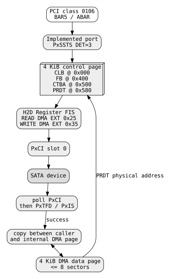
ChrisOS implements a compact AHCI storage path for SATA disks exposed through a PCI AHCI controller. The implementation is deliberately narrower than the full AHCI specification: it discovers one usable controller and one usable port, configures one command slot, allocates one page for command structures and one page for data, builds host-to-device register FIS structures directly, issues DMA EXT commands, and polls command completion through the port command-issue register.
The current driver is synchronous and single-request. It does not implement Native Command Queuing, multiple active slots, interrupt-driven completion, hotplug, port multipliers, ATAPI, controller reset, or explicit cache flush. Its purpose is to provide a simple SATA DMA path behind the common ChrisOS BlockDevice contract.
This chapter describes ChrisOS revision e05a17fd76333114a3fb5c2452f38ca747d4ac56.
AHCI in the storage architecture
The block layer above AHCI sees a normal 512-byte sector device:
ChrisFS / partition layer
        -> BlockDevice
        -> ahci_read / ahci_write
        -> ahci_rw
        -> issue
        -> AHCI port registers + DMA command structures
        -> SATA device
storage_init probes legacy ATA first and AHCI immediately afterward. A discovered AHCI device is registered as BD_AHCI. Root selection is not based on transport preference alone: the storage layer searches registered non-RAM devices for an existing ChrisFS filesystem or partition and can choose AHCI as root when appropriate.
The standalone test-qemu-ahci gate normally keeps the ordinary IDE disk as the existing root and adds a second AHCI disk so that the generic destructive-safe read/write test can exercise AHCI as a non-root device. A separate test-qemu-noata path demonstrates an AHCI disk becoming the root device when legacy ATA is unavailable.
Standard AHCI model
AHCI moves SATA command execution away from legacy task-file port I/O and into a memory-mapped host controller interface. A host bus adapter exposes global registers and one register block per implemented port. The operating system gives a port physical addresses for:
- a command list;
- a received-FIS area;
- one or more command tables;
- PRDT entries that describe DMA buffers.
A command slot in the command list points at a command table. The command table contains the command FIS and its physical-region descriptors. The driver then sets a bit in PxCI, the port command-issue register. Hardware fetches the command structures through DMA, transfers data, updates status, and clears the command-issue bit when the slot is no longer active.
ChrisOS implements exactly one active slot: slot 0.
Driver state
The private AhciPort structure stores:
| Field | Meaning |
|---|---|
win |
mapped MMIO window for the AHCI BAR |
base |
offset of the selected port register block |
ctl |
DMA allocation ID for command/control structures |
data |
DMA allocation ID for the transfer buffer |
sectors |
exposed logical sector count |
There is one global instance, g_port, and one global ready flag. Once a usable disk is registered, subsequent ahci_probe calls return immediately.
This design avoids dynamic per-device objects but also means the driver represents only one AHCI disk.
PCI discovery
ahci_probe searches PCI buses 0 through 7, devices 0 through 31, and functions 0 through 7. It reads class information from configuration offset 8 and accepts functions whose class/subclass is 0x0106, the AHCI SATA controller class.
When a candidate is found, ChrisOS updates the PCI command register with:
which sets memory-space enable and bus-master enable.
The driver maps BAR5 using hw_bar_map. In conventional AHCI hardware, BAR5 is the AHCI base address register, usually called ABAR. hw_bar_map accepts memory BARs, handles 64-bit BAR addressing when present, temporarily sizes the BAR, maps enough MMIO pages into the kernel, and returns an internal MMIO-window ID.
The generic hardware gate caps one mapped window to 64 pages, or 256 KiB. AHCI itself usually needs far less than that.
Enabling AHCI mode
After mapping BAR5, the driver sets bit 31 of the global host-control register at MMIO offset 0x04:
This enables AHCI mode.
It then reads PI, Ports Implemented, at offset 0x0c. Every set bit marks a port implemented by the controller. The driver examines ports 0 through 31 in ascending order.
A port register block begins at:
Only implemented ports are considered.
Link detection
For each implemented port, ChrisOS reads PxSSTS at port offset 0x28. The driver tests only the low four DET bits and requires:
which corresponds to a device being present with communication established.
The current code does not additionally validate the interface-power-management field or PxSIG. It therefore does not explicitly distinguish SATA disks from ATAPI devices using the signature register before issuing IDENTIFY. A candidate that does not respond as expected is simply skipped later.
DMA memory topology
For a candidate port the driver allocates two contiguous physical pages through hw_dma_alloc(1):
ctl: one 4096-byte page for the command list, received-FIS area and command table;data: one 4096-byte page for payload data.
Unlike the legacy ATA Bus Master path, these allocations are not restricted to addresses below 4 GiB. AHCI command structures carry low and high 32-bit halves of physical addresses, and the driver writes both halves with hw_dma_lo and hw_dma_hi.
The control page is partitioned by fixed offsets:
0x000  command list; slot 0 command header is here
0x400  received-FIS area
0x500  command table for slot 0
0x580  first PRDT entry inside that command table
Only slot 0 is used, so most of the command-list page remains unused.
The data page holds at most 4096 bytes. At 512 bytes per logical sector, one command can therefore transfer no more than eight sectors.
Port start sequence
start_port first reads PxCMD at offset 0x18. It clears:
- bit 0,
ST, command-list running; - bit 4,
FRE, FIS receive enable.
It writes the modified value and waits until both engine-status bits clear:
- bit 15,
CR, command-list running; - bit 14,
FR, FIS receive running.
wait_bit polls for at most 200000 iterations. Failure returns an error to the probe.
After the engines stop, ChrisOS writes the 64-bit physical address of the control page into PxCLB/PxCLBU. It places the received-FIS area at control_page + 0x400 and writes that address into PxFB/PxFBU.
It clears PxSERR by writing all ones at port offset 0x30, then re-enables FRE and ST.
This is a minimal engine restart. It is not a full HBA reset or SATA COMRESET sequence.
Building the command header
Before every command, issue zeroes all 4096 bytes of the control page. This clears the previous command header, received-FIS storage and command table in one pass.
The first dword of slot 0's command header is set to:
These fields encode:
- command-FIS length = 5 dwords = 20 bytes;
- write-direction flag when the host sends data to the device;
- PRDT length = 1.
The command-table physical address is written into header offsets 8 and 12 as low/high halves. It points to control_page + 0x500.
The implementation therefore uses one command header and exactly one PRDT entry for every request.
Host-to-device Register FIS
The command table begins with a Register Host-to-Device FIS. ChrisOS writes its first dword as:
This encodes:
- FIS type
0x27; - the command/control bit in byte 1;
- the ATA command opcode in byte 2.
The next dword contains the low 24 bits of LBA plus device byte 0x40, selecting LBA addressing. The next dword contains LBA bits 24 through 47. Sector count is written into FIS bytes 12-13.
The source contains a specific correction documenting that sector count belongs in bytes 12-13, not in the expanded-features byte. This matters because malformed FIS field placement can look superficially valid while causing controllers to execute the wrong transfer length.
Data commands and addressability
Normal reads use ATA opcode 0x25, READ DMA EXT. Writes use 0x35, WRITE DMA EXT. These are 48-bit LBA commands.
This differs materially from the legacy ATA PIO/Bus Master path documented in the preceding chapter, which currently issues 28-bit data commands.
The FIS builder can encode 48 LBA bits, but ChrisOS passes lba as a uint32_t, and BlockDevice.sector_count is also 32-bit. Therefore the software-visible capacity remains limited to at most 2^32 sectors. With 512-byte sectors that is approximately 2 TiB, even though the AHCI/SATA command format itself can address much more.
PRDT construction
The single PRDT entry is placed at command-table offset 0x80, which corresponds to control-page offset 0x580.
ChrisOS writes:
- data-buffer physical address low 32 bits;
- data-buffer physical address high 32 bits;
- byte count minus one;
- interrupt-on-completion bit in the high bit of the byte-count field.
Conceptually:
Even though IOC is set, the current driver does not use an AHCI interrupt handler for request completion. Completion is polled through PxCI.
The PRDT entry always describes a single physically contiguous buffer. No scatter/gather list is built.
Issuing a command
Immediately before issuing the slot, the driver writes all ones to PxIS at port offset 0x10, clearing pending port-interrupt status bits.
It then writes 1 to PxCI at offset 0x38, activating slot 0.
The driver polls up to 500000 iterations. Every 128 iterations it calls io_wait. Completion is recognized when bit 0 of PxCI becomes zero.
Once the slot clears, ChrisOS reads:
PxTFDat offset0x20;PxISat offset0x10.
If bit 0 of PxTFD is set, the driver prints both values and reports an I/O failure. Otherwise it reports success.
If the loop expires while PxCI remains set, issue returns its timeout code.
Synchronous read path
ahci_read delegates to ahci_rw with write mode disabled.
The high-level loop breaks a request into chunks of at most eight sectors. For each chunk it calls issue with READ DMA EXT. When the controller completes successfully, the driver copies the data page into the caller's buffer as 32-bit words.
For each four-byte word, hw_dma_r32 reads from the mapped DMA page and the driver splits that value into four bytes.
The asymptotic CPU-copy cost is linear in the number of transferred bytes, O(n). SATA payload movement itself is DMA, but this driver is not zero-copy because all reads are copied from the internal data page into the caller buffer.
Synchronous write path
Writes perform the reverse copy first. The caller's bytes are packed into 32-bit values and written into the internal data page with hw_dma_w32. The driver then issues WRITE DMA EXT.
After command completion, the high-level write returns BD_OK without sending an explicit ATA FLUSH CACHE command.
The resulting BlockDevice sets:
and generic bd_flush treats a missing callback as success. Therefore the current AHCI backend does not expose an explicit device-cache flush boundary. Successful command completion establishes that the controller completed the write command, but the ChrisOS block API currently does not separately force volatile drive cache contents to stable media through this driver.
This distinction is important for filesystem crash-consistency claims.
Error normalization
issue has two internal failure forms:
- ordinary failure, including task-file error;
- timeout while waiting for
PxCIto clear.
ahci_rw converts them into the common block-device domain:
| Internal result | Block result |
|---|---|
| success | BD_OK |
| timeout | BD_ETIMEOUT |
| other command failure | BD_EIO |
Generic argument and range checks occur above the driver in bd_read and bd_write.
The implementation does not decode detailed SATA error information from the received D2H FIS or PxSERR after a failed command. Diagnostic output is limited to PxTFD and PxIS in the task-file-error path.
Probe-time IDENTIFY
After starting a candidate port, ChrisOS reuses the same generic command path to issue IDENTIFY DEVICE (0xec) for one sector.
The 512-byte identify payload is then viewed as 128 32-bit words. Because each 32-bit value contains two ATA identify words:
- array element 50 corresponds to ATA words 100-101, the low 32 bits of the LBA48 sector count;
- array element 51 corresponds to ATA words 102-103, the high 32 bits;
- array element 30 corresponds to ATA words 60-61, the legacy 28-bit sector count.
If element 51 is nonzero, the driver prints ahci disk too large and rejects the device because the current block interface cannot represent the full capacity.
Otherwise it first uses element 50. If that value is below 2048 sectors, it falls back to element 30. Devices still smaller than 2048 sectors are skipped.
This is a pragmatic capacity extraction path rather than a complete parser for ATA IDENTIFY capabilities.
Registration and root selection
A successful device becomes a writable 512-byte BlockDevice with the AHCI callbacks and no flush callback. It is registered under the name ahci with kind BD_AHCI, and the driver prints:
The driver then stops scanning and returns success. Additional ports or additional AHCI controllers are not registered.
Root selection happens later in the generic storage layer. Consequently AHCI may be:
- a secondary non-root disk;
- the root disk when it contains the selected ChrisFS instance;
- an installation target when marked eligible by the block registry rules.
Concurrency and ownership
The AHCI specification supports many command slots and, with NCQ, substantial parallelism. ChrisOS does not expose that parallelism.
There is one global port object, one control page, one data page and slot 0 only. Every command zeroes and rewrites the same memory structures. There is no mutex or spinlock in the AHCI driver.
The required software invariant is therefore one caller at a time. Concurrent requests could corrupt:
- the command header;
- the H2D FIS;
- the PRDT;
- the data bounce page;
- the
PxCIcompletion state.
The synchronous block stack currently tends to preserve this assumption, but the driver itself does not enforce it.
Timeout and recovery semantics
Finite polling prevents an indefinitely stuck controller from hanging the caller forever, but timeout handling is incomplete.
When a command times out, the driver returns BD_ETIMEOUT. It does not:
- clear or abort the active command slot;
- stop and restart the command engine;
- issue a port reset;
- perform COMRESET;
- reset the HBA;
- prove that the controller can no longer DMA into the shared data page.
That last point is an ownership concern. After a timeout, robust DMA recovery should establish that the old command has stopped before the buffer is safely reused. The current code lacks that explicit recovery proof.
This is one of the more important hardening gaps in the driver.
Probe resource lifetime
Two one-page DMA allocations are created for every candidate port that reaches the allocation stage.
If allocation itself fails, the code frees the IDs it received. However, after both allocations succeed, several later rejection paths — failed start_port, failed IDENTIFY, unsupported large capacity or too-small capacity — continue scanning without releasing those pages.
That creates a bounded but real probe-time resource leak for rejected candidate ports. The global hardware DMA allocator has a finite number of slots, so this behavior should be corrected before the probe becomes broader or supports many controllers.
Safety and privilege
AHCI requires privileged PCI configuration, MMIO mapping and bus-master DMA. The driver executes entirely inside the kernel.
Safety mechanisms currently include:
- block-layer LBA range validation;
- bounded polling loops;
- MMIO access through a bounded mapped-window abstraction;
- DMA buffers allocated from physically contiguous kernel-owned memory;
- full 64-bit physical addresses in AHCI structures;
- request size capped to the one-page data buffer.
Missing protections include IOMMU isolation, per-request DMA mapping, robust timeout teardown and controller locks.
A corrupted command table or incorrect physical address can instruct the HBA to DMA into arbitrary physical memory visible to the device.
Performance characteristics
The hardware path uses SATA DMA, but the software architecture imposes several throughput limits:
- maximum 4 KiB payload per command;
- one PRDT entry;
- one active slot;
- no NCQ;
- polling instead of interrupt-driven sleep/wakeup;
- full CPU copy into or out of the internal DMA page;
- command structures zeroed across an entire 4 KiB page for every request.
For sequential requests larger than eight sectors, ahci_rw repeatedly submits independent commands. The number of controller submissions therefore grows as approximately:
This favors implementation simplicity and deterministic memory ownership over AHCI's potential queue depth and throughput.
Validation evidence
The source tree contains two especially relevant QEMU gates.
Dedicated secondary-disk gate
test-qemu-ahci creates a 32 MiB zeroed image and attaches it through QEMU's ICH9 AHCI controller. The gate requires:
The generic bdev_rw_tests routine reads the last sector, writes a deterministic pattern, reads it back, verifies every byte and restores the original sector. Because the ordinary IDE disk remains root in this topology, the AHCI disk is eligible for this non-root destructive-with-restoration test.
This validates discovery plus a complete AHCI write/read round trip through the block layer.
AHCI root gate
test-qemu-noata boots with the root disk attached to AHCI and requires:
That path is stronger evidence for filesystem integration: AHCI supplies the selected root block device, ChrisFS mounts from it, and the system continues into later boot stages.
The tests establish behavior for the QEMU ICH9 AHCI model under the tested configuration. They are not evidence of broad physical SATA-controller compatibility.
Current limitations
At the documented revision, the AHCI path supports only a narrow subset:
- one registered AHCI disk;
- one selected port;
- command slot 0 only;
- one PRDT entry;
- maximum eight sectors per command;
- one internal 4 KiB data buffer;
- synchronous polling completion;
- no AHCI interrupt handler;
- no NCQ;
- no multi-request queue;
- no ATAPI;
- no port multiplier;
- no hotplug;
- no explicit
PxSIGdevice-type validation; - no explicit cache-flush command;
- no 4 KiB logical-sector support;
- no robust command-abort or timeout recovery;
- no HBA reset or COMRESET recovery path;
- no driver-level locking;
- no enumeration of additional working AHCI ports after the first disk;
- 32-bit logical sector count, limiting exposed capacity to roughly 2 TiB at 512 bytes per sector;
- incomplete cleanup of DMA allocations on rejected probe candidates.
These are implementation limits, not limits of AHCI or SATA as standards.
Roadmap boundary
A more complete implementation could add per-port objects, slot allocation, PRDT scatter/gather, interrupt-driven completions, NCQ, explicit FLUSH CACHE EXT, signature validation, hotplug, error-FIS decoding, robust timeout cancellation, HBA/port reset recovery, cleanup on failed probes, controller locking and validation on physical SATA hardware.
Those capabilities are future work until source and reproducible evidence establish them.
Source map and revision note
kernel/fs/ahci.c contains discovery, port setup, command construction, DMA transfers and block adaptation. kernel/fs/ahci.h exposes the probe entry point. kernel/gfx/hwgate.c provides the MMIO-window and physically contiguous DMA abstractions used by the driver. kernel/fs/block_device.h and kernel/fs/bdev.c provide the common block contract and registry. kernel/fs/storage.c integrates AHCI into root discovery, formatting and block-device validation. scripts/qemu.mk defines the dedicated AHCI and AHCI-root gates.
All current-behavior claims in this chapter were reconciled against ChrisOS e05a17fd76333114a3fb5c2452f38ca747d4ac56.