
NVMe queues and namespaces
About this chapter Block transport and media
In this chapter
- NVMe queues and namespaces
- Scope
- Position in the storage stack
- NVMe queue model
- Driver state
- PCI discovery
- CAP and doorbell stride
- Controller disable sequence
- DMA allocations
- Admin Queue Attributes
- Enabling the controller
- Queue indices and phase tags
- Admin command construction
- Completion processing
- Identify Controller
- Creating the I/O Completion Queue
- Creating the I/O Submission Queue
- Namespace identification
- LBA format assumption
- Namespace policy
- I/O command format
- One-page PRP transfer limit
- Read path
- Write path
- Queue concurrency
- Timeout behavior
- Initialization failure cleanup
- Controller lifecycle gaps
- Security and privilege
- Performance characteristics
- Validation evidence
- Current limitations
- Roadmap boundary
- Source map and revision note
Scope
ChrisOS contains a compact NVMe driver that discovers one PCI NVMe controller, creates a two-entry Admin Submission Queue and Admin Completion Queue, creates one two-entry I/O Submission Queue and I/O Completion Queue, identifies controller namespace count, identifies namespace 1, and exposes that namespace as a writable 512-byte BlockDevice.
The implementation intentionally exercises the queue and doorbell model directly instead of hiding NVMe behind a firmware interface. It programs the controller through MMIO, allocates physically contiguous queue memory, constructs 64-byte submission commands, observes 16-byte completion entries with phase tags, and transfers payload data through one 4 KiB PRP buffer.
The current path is much narrower than NVMe as a standard. It supports one controller, namespace 1 only, queue identifier 1 only, one command outstanding at a time, one PRP data page, polling rather than MSI/MSI-X completion, and no explicit NVMe Flush command. It does not implement namespace enumeration, multiple I/O queues, queue-depth scaling, PRP lists, SGLs, controller reset recovery, asynchronous events, power management, or multipath behavior.
This chapter documents ChrisOS revision e05a17fd76333114a3fb5c2452f38ca747d4ac56.
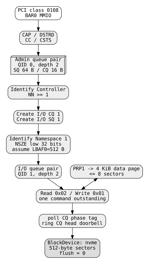
Position in the storage stack
The storage stack sees NVMe through the same block contract used by ATA, AHCI, VirtIO Block and USB mass storage:
ChrisFS / GPT / generic storage
        -> BlockDevice
        -> nvme_read / nvme_write
        -> nvme_rw
        -> I/O SQ entry
        -> NVMe controller
        -> I/O CQ entry
        -> internal 4 KiB data page
storage_init probes NVMe after ATA and AHCI and before VirtIO Block and USB mass storage. A successful probe registers a device named nvme with kind BD_NVME.
Root selection happens later in generic storage code. The NVMe transport itself does not decide whether its namespace is the root disk.
NVMe queue model
NVMe is designed around queue pairs. The host writes commands into a Submission Queue (SQ). The controller writes completion records into a Completion Queue (CQ). The host and controller coordinate positions through queue indices, completion phase tags and MMIO doorbells.
ChrisOS creates two pairs:
| Queue pair | Queue ID | Entries | Entry sizes | Purpose |
|---|---|---|---|---|
| Admin SQ/CQ | 0 | 2 | SQ 64 B, CQ 16 B | Identify and create I/O queues |
| I/O SQ/CQ | 1 | 2 | SQ 64 B, CQ 16 B | Read and write namespace 1 |
The queue size programmed into NVMe commands and AQA is zero-based. A field value of 1 therefore means two entries.
Although the hardware queues each have two entries, ChrisOS serializes requests and waits synchronously after every submission. Effective in-flight depth is therefore one.
Driver state
The global Nvme object stores:
| Field | Role |
|---|---|
win |
mapped MMIO window for controller BAR0 |
stride |
byte spacing between doorbell registers |
admin_sq, admin_cq |
DMA allocation IDs for admin queues |
io_sq, io_cq |
DMA allocation IDs for I/O queues |
data |
one-page data/identify buffer |
asq_tail, acq_head |
Admin SQ tail and CQ head |
isq_tail, icq_head |
I/O SQ tail and CQ head |
cid |
monotonically incrementing 16-bit command identifier |
admin_phase, io_phase |
expected CQ phase bits |
sectors |
exposed logical sector count |
There is one global controller object, g_nv, and one ready flag. Once a namespace is registered, later probes return success without scanning again.
PCI discovery
nvme_probe scans PCI buses 0 through 7, devices 0 through 31 and functions 0 through 7.
It accepts a PCI function when the class/subclass pair read from configuration space equals:
which identifies an NVM Express controller.
The PCI command register is updated with | 6, enabling memory-space decoding and bus mastering. BAR0 is then mapped through hw_bar_map.
The current driver assumes the controller's NVMe MMIO register set is reachable through BAR0. It does not inspect alternative vendor-specific mappings.
CAP and doorbell stride
The 64-bit CAP register is read from offsets 0x00 and 0x04.
ChrisOS extracts DSTRD from CAP bits 35:32 and computes:
The result is the byte spacing between successive doorbells.
NVMe doorbells begin at controller offset 0x1000. For queue ID 0 and queue ID 1, ChrisOS computes:
Admin SQ tail: 0x1000 + 0 * stride
Admin CQ head: 0x1000 + 1 * stride
I/O SQ tail:   0x1000 + 2 * stride
I/O CQ head:   0x1000 + 3 * stride
ring_sq and ring_cq encapsulate these writes.
The driver does not currently consume other important CAP fields such as maximum queue entries, controller timeout, minimum/maximum page size, command-set support or controller memory buffer capabilities.
Controller disable sequence
Before configuring queues, the driver reads CC at offset 0x14 and clears bit 0, CC.EN.
It then polls CSTS at 0x1c for up to 200000 iterations, looking for:
This is the standard high-level requirement before reprogramming Admin Queue attributes and addresses.
There is, however, an important implementation limitation: after the loop finishes, the code does not verify whether the condition was actually reached. If the loop exhausts with RDY still set, initialization continues anyway.
The same issue exists during controller enable later in the probe.
DMA allocations
Five one-page physically contiguous DMA allocations are created:
- Admin Submission Queue;
- Admin Completion Queue;
- I/O Submission Queue;
- I/O Completion Queue;
- data/identify buffer.
Each page is 4096 bytes. Queue memory is therefore significantly larger than the two entries actually used, but the simple fixed-size allocation avoids queue-memory packing.
hw_dma_alloc may allocate physical memory above 4 GiB. NVMe queue base registers and PRP addresses are 64-bit, and ChrisOS writes both low and high halves.
If any allocation fails, the probe attempts to free all five IDs and skips that candidate controller.
Admin Queue Attributes
ChrisOS writes AQA at offset 0x24 as:
The low field is ASQS and the high field is ACQS. Both are zero-based queue sizes, so each admin queue contains two entries.
The physical address of the Admin Submission Queue is written into ASQ at offsets 0x28/0x2c, and the Admin Completion Queue into ACQ at 0x30/0x34.
Both queues occupy their own page, even though only 128 bytes of SQ storage and 32 bytes of CQ storage are required for a depth of two.
Enabling the controller
The driver programs CC with:
This sets:
EN = 1;IOSQES = 6, meaning 2^6 = 64-byte I/O Submission Queue entries;IOCQES = 4, meaning 2^4 = 16-byte Completion Queue entries.
Other fields remain zero, including the memory page size field, so the implementation assumes the controller accepts the default 4 KiB page size.
After writing CC, the driver polls for CSTS.RDY == 1 for up to 200000 iterations.
As in the disable path, loop exhaustion is not checked explicitly. A controller that never becomes ready can therefore cause the driver to proceed into Admin commands instead of being rejected immediately.
Queue indices and phase tags
Both SQ tails and CQ heads begin at zero because g_nv is static storage.
Admin and I/O completion phases are initialized to 1. Newly zeroed completion memory has phase bit 0, so the driver will not mistake an untouched CQ entry for a new completion.
When wait_cq sees the expected phase bit in completion DW3, it consumes the entry, advances the CQ head modulo two, and toggles the expected phase whenever the head wraps from entry 1 back to entry 0.
Conceptually:
The CQ head doorbell is then rung to tell the controller the completion was consumed.
This is a correct use of the NVMe phase-tag mechanism for a tiny circular queue.
Admin command construction
admin_cmd selects the current Admin SQ entry from:
It zeroes all 64 bytes, increments the global 16-bit command ID, and writes:
- opcode and CID into command dword 0;
- namespace ID into dword 1;
- PRP1 low/high into dwords 6-7;
- CDW10;
- CDW11.
The tail is advanced modulo two and the Admin SQ tail doorbell is rung.
The function then immediately calls wait_cq, so there is never more than one outstanding Admin command.
The implementation does not validate that the completion CID matches the submitted CID. With exactly one command in flight this normally works, but explicit CID matching would make corruption and stale-completion detection stronger.
Completion processing
Each Completion Queue entry is 16 bytes. wait_cq reads dword 3 at:
It tests bit 16 as the phase tag. Once the expected phase appears, status is derived from bits 31:17.
A zero status returns success; any nonzero status becomes a generic failure.
The driver currently ignores:
- completion result dword 0;
- SQ head reported by the completion;
- SQ identifier;
- command identifier;
- detailed Status Code Type and Status Code interpretation.
That keeps the implementation compact but loses diagnostic information and protocol cross-checking.
If no completion with the expected phase arrives within 400000 polls, wait_cq returns a timeout.
Identify Controller
The first Admin command after enable is opcode 0x06, Identify, with:
CNS 1 requests Identify Controller.
ChrisOS reads the controller's NN field at byte offset 516 from the returned data page. NN is the number of namespaces.
The driver requires only:
It does not enumerate namespace IDs. The value is used only to reject a controller reporting zero namespaces.
Creating the I/O Completion Queue
The driver sends Admin opcode 0x05, Create I/O Completion Queue.
PRP1 points to the physical page allocated for io_cq.
CDW10 is:
meaning queue ID 1 and queue size field 1, which gives a two-entry queue.
CDW11 is 1, setting the physically-contiguous flag. Interrupt enable is not set, consistent with the polling design.
Creating the I/O Submission Queue
Next, Admin opcode 0x01, Create I/O Submission Queue, creates SQ 1.
CDW10 again selects queue ID 1 with a two-entry size.
CDW11 is:
The low bit marks physically contiguous queue memory. The field beginning at bit 16 selects Completion Queue ID 1, associating this SQ with the previously created CQ.
No queue-priority policy beyond the zero/default field is configured.
Namespace identification
ChrisOS issues another Identify command:
CNS 0 requests Identify Namespace for namespace 1.
The namespace size NSZE is a 64-bit value at the beginning of the structure. ChrisOS reads the low 32 bits at offset 0 and rejects the namespace when the high 32 bits at offset 4 are nonzero.
This is a software-capacity limitation, not an NVMe limitation. The common BlockDevice interface stores both LBA and sector count in uint32_t.
At 512 bytes per block, a 32-bit sector count represents at most approximately 2 TiB.
LBA format assumption
The namespace identify structure can describe multiple LBA formats, and the active one is selected by FLBAS.
ChrisOS currently reads only the first LBA Format Data Structure at byte offset 128 and tests:
Since logical block size is 2^LBADS, this means 512-byte blocks.
The driver does not read FLBAS to determine which LBA format is actually active. It effectively assumes LBAF0 is the current format.
Therefore a namespace exposing LBAF0 as 512 bytes but actively formatted with a different LBAF is not correctly characterized by the current probe.
A complete implementation should read FLBAS, select the corresponding LBAF entry, then validate metadata and protection-information requirements as well.
Namespace policy
Only namespace 1 is ever attached.
Even if Identify Controller reports multiple namespaces, the driver does not:
- request an active namespace ID list;
- iterate namespace IDs;
- register more than one namespace;
- distinguish inactive from active namespace configurations beyond whether Identify Namespace succeeds.
This is adequate for the single-namespace QEMU test model but is not general namespace management.
I/O command format
io_rw builds one 64-byte I/O Submission Queue command.
For reads, opcode is:
For writes:
The command always uses:
The upper 32 bits of starting LBA are left zero. This matches the surrounding 32-bit block API.
No PRP2 value or PRP list is supplied.
One-page PRP transfer limit
The internal data buffer is one 4096-byte page and the block size is fixed at 512 bytes.
Consequently:
nvme_rw explicitly caps every I/O command to eight sectors. Larger caller requests are split into sequential commands.
For N sectors, the submission count is approximately:
This avoids PRP chaining and page-boundary complexity at the cost of throughput.
Read path
For each chunk, nvme_rw submits a Read command and waits synchronously for its completion.
After a successful completion, the driver copies the internal DMA page into the caller's buffer in 32-bit units through hw_dma_r32.
The device transfer is DMA, but the interface is not zero-copy. CPU work is still linear in transferred bytes because of the bounce copy.
Write path
Writes first pack caller bytes into the internal DMA page through hw_dma_w32.
The driver submits the NVMe Write command, rings the I/O SQ doorbell and polls the I/O CQ until completion.
The registered block device has:
No NVMe Flush command is issued by this backend, and the generic block helper treats a missing flush callback as success.
Therefore successful ChrisOS NVMe writes do not currently provide an explicit API operation that forces volatile controller/device write cache contents to nonvolatile media. Filesystem durability claims must account for that missing barrier.
Queue concurrency
NVMe is specifically designed to support deep queues and multiple queues per CPU. The current ChrisOS driver intentionally does not use that architecture for concurrency.
Only one command is submitted before waiting for completion. There is:
- one global data page;
- one global I/O SQ;
- one global I/O CQ;
- no command table per caller;
- no lock around queue state;
- no interrupt-driven completion path.
Concurrent callers could race on the SQ tail, CQ head, phase state, command IDs and data page.
The practical invariant is one active request at a time.
Timeout behavior
wait_cq polls at most 400000 iterations. If no expected phase-tagged completion appears, it returns -2.
The read/write layer converts this to BD_ETIMEOUT. Other nonzero completion status becomes BD_EIO.
The timeout path does not perform controller recovery. It does not:
- delete and recreate queues;
- disable the controller and confirm RDY clears;
- reset queue indices;
- guarantee an old command can no longer DMA;
- identify whether the timed-out command eventually completed;
- quarantine the shared data page.
This means timeout recovery is weaker than the submission path itself. Reusing queue or data memory after an ambiguous timeout can violate DMA ownership assumptions.
Initialization failure cleanup
If initial DMA allocation fails, the driver frees the queue/data allocations.
However, after all five allocations succeed, many later failure paths simply continue the PCI scan:
- Identify Controller failure;
- zero namespaces;
- Create I/O CQ failure;
- Create I/O SQ failure;
- Identify Namespace failure;
- capacity too large;
- unsupported assumed sector size;
- namespace too small.
Those paths do not release the five DMA allocations or tear down created controller queues.
As with the current AHCI probe, this is a bounded but real resource-lifetime gap. It becomes more significant if discovery is expanded to multiple controllers or repeated probe attempts.
Controller lifecycle gaps
The current probe programs the controller directly but does not model the full lifecycle state machine.
Notably it does not:
- test
CSTS.CFSfor fatal controller state; - use CAP.TO to derive controller-specific timeout duration;
- validate CAP.MQES against the requested queue size;
- validate CAP.MPSMIN/MPSMAX against the 4 KiB assumption;
- issue Delete I/O SQ/CQ commands during teardown;
- perform a subsystem reset;
- recover after fatal status;
- configure MSI or MSI-X.
These are implementation boundaries, not protocol deficiencies.
Security and privilege
The driver operates with kernel privilege and enables PCI bus mastering.
The controller receives physical addresses for queues and PRP buffers and can DMA to them. ChrisOS currently does not place the NVMe device behind an IOMMU mapping domain.
Relevant safeguards include:
- bounded MMIO windows;
- physically contiguous kernel-owned queue pages;
- explicit 64-bit queue/PRP addresses;
- block-layer LBA range checks;
- fixed one-page payload size;
- finite polling loops.
Missing isolation includes IOMMU confinement, per-request DMA mapping and strong recovery that proves DMA has stopped after timeout.
Performance characteristics
The current driver demonstrates NVMe semantics rather than NVMe-class throughput.
Main bottlenecks are:
- queue depth effectively 1;
- only one I/O queue pair;
- two entries per queue;
- maximum 4 KiB per command;
- only PRP1;
- synchronous polling;
- CPU bounce copies;
- no batching;
- no per-CPU queues;
- no interrupt moderation or MSI-X;
- no large I/O aggregation.
A modern NVMe controller can support many queues, deep queue depths and much larger transfers. ChrisOS currently chooses simplicity and explicit state over performance.
Validation evidence
scripts/qemu.mk contains a dedicated test-qemu-nvme gate.
It creates a 32 MiB image and attaches it through QEMU's NVMe device:
The gate requires both:
The generic bdev_rw_tests function exercises the final sector of every writable non-root block device. It:
- reads the original sector;
- writes a deterministic byte pattern;
- reads the sector back;
- compares all 512 bytes;
- restores the original sector.
Because the normal IDE disk remains root in this gate, the NVMe device is eligible for this round-trip test.
This is direct evidence that, under the QEMU model used by the project, PCI discovery, controller initialization, admin commands, I/O queue creation, namespace identification, PRP data transfer, write completion and read completion function together.
It is not evidence of broad compatibility with physical NVMe controllers.
Current limitations
At the documented revision, the implementation is limited to:
- one registered NVMe controller/device;
- namespace 1 only;
- no namespace enumeration;
- Admin queue depth 2;
- one I/O queue pair with depth 2;
- one outstanding command in practice;
- polling completion only;
- no MSI/MSI-X;
- one 4 KiB PRP buffer;
- PRP1 only, no PRP2 or PRP list;
- maximum eight 512-byte sectors per command;
- only 512-byte logical blocks;
- LBAF0 assumed active without consulting FLBAS;
- 32-bit block LBA and sector count, limiting exposed capacity to roughly 2 TiB;
- no explicit Flush command;
- no detailed completion-status decoding;
- no CID validation on completion;
- no CAP.MQES/MPS/TO validation;
- no
CSTS.CFShandling; - enable/disable polling loops that do not verify timeout exhaustion;
- no controller/queue recovery after command timeout;
- no locking for concurrent callers;
- incomplete resource cleanup on probe failures after DMA allocation;
- no teardown or Delete I/O Queue path;
- no physical-hardware compatibility evidence in the documented gate.
Roadmap boundary
A fuller driver could add namespace-list discovery, FLBAS-aware format selection, multiple namespaces, controller-capability validation, robust RDY timeout checks, MSI-X, per-CPU queue pairs, deeper queues, CID-tracked outstanding requests, PRP2/PRP lists, larger transfers, explicit Flush support, detailed completion decoding, reset recovery, IOMMU-backed DMA isolation and physical-device validation.
Those capabilities remain future work until implemented and covered by reproducible evidence.
Source map and revision note
kernel/fs/nvme.c contains PCI discovery, controller setup, admin commands, queue management, namespace identification and block I/O. kernel/fs/nvme.h exposes the probe entry point. kernel/gfx/hwgate.c supplies MMIO and physically contiguous DMA allocation. kernel/fs/block_device.h defines the generic block contract. kernel/fs/bdev.h and kernel/fs/bdev.c register the device as BD_NVME. kernel/fs/storage.c integrates it into root discovery and generic read/write validation. scripts/qemu.mk defines the NVMe QEMU gate.
All claims about current ChrisOS behavior in this chapter were reconciled against revision e05a17fd76333114a3fb5c2452f38ca747d4ac56.