
ATA PIO and Bus Master IDE DMA
About this chapter Block transport and media
In this chapter
- ATA PIO and Bus Master IDE DMA
- Scope
- Position in the storage stack
- ATA task-file interface
- Driver state and ownership
- Discovery and IDENTIFY
- Command programming
- Polling and bounded failure
- PIO read path
- PIO write and persistence
- Bus Master IDE discovery
- DMA memory model and PRDT
- DMA transfer sequence
- Completion, IRQ and timeout
- DMA failure and PIO fallback
- Error model and recovery limits
- Addressability boundaries
- Privilege and safety
- Performance trade-offs
- Validation evidence
- Current limitations
- Roadmap boundary
- Source map and revision note
Scope
The ChrisOS ATA path is a compatibility-oriented block-storage driver for legacy IDE task-file interfaces. It supports two transfer mechanisms behind the same BlockDevice: programmed I/O through the ATA data port and PCI Bus Master IDE DMA through a physical region descriptor table. The driver discovers devices with IDENTIFY DEVICE, normalizes controller errors into the BD_* domain, and falls back from DMA to PIO after aborting and resetting the channel.
This chapter describes ChrisOS revision e05a17fd76333114a3fb5c2452f38ca747d4ac56. It deliberately separates implemented behavior from ATA features defined by later standards. The current data commands are the 28-bit opcodes READ SECTORS, WRITE SECTORS, READ DMA and WRITE DMA; 48-bit extended data commands are not issued.
Position in the storage stack
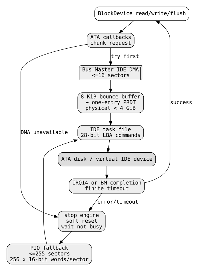
storage_init owns one global AtaPio object, configures it, probes for a disk, converts it into a BlockDevice, and registers it as BD_ATA. ChrisFS and partition code therefore consume the same sector-oriented interface used by AHCI, NVMe and VirtIO Block.
The control path is:
ChrisFS / partition view
        -> BlockDevice
        -> ata_bd_read / ata_bd_write / ata_bd_flush
        -> Bus Master IDE DMA when available
              or
           ATA PIO fallback
        -> IDE task-file registers
        -> physical or virtual ATA device
The generic block layer checks that requests stay inside sector_count and that the device reports 512-byte logical sectors. The ATA implementation assumes the same sector size in PIO loops, DMA byte counts and buffer increments.
ATA task-file interface
The driver uses the classic command block relative to AtaPio.io:
| Offset | Register | Current use |
|---|---|---|
| 0 | DATA | 16-bit PIO payload transfers |
| 2 | SECTOR COUNT | sectors in the command |
| 3 | LBA0 | LBA bits 0-7 |
| 4 | LBA1 | LBA bits 8-15 |
| 5 | LBA2 | LBA bits 16-23 |
| 6 | DRIVE/HEAD | master/slave, LBA mode, LBA bits 24-27 |
| 7 | STATUS / COMMAND | status reads and command writes |
The alternate-status/control port is stored in AtaPio.ctrl. ChrisOS probes the traditional primary channel at 0x1f0/0x3f6 and secondary channel at 0x170/0x376.
Four status bits drive the state machine:
ERR(0x01) reports a command error;DRQ(0x08) means a data phase is ready;DF(0x20) reports device fault;BSY(0x80) means the command is still active.
The driver maps ERR or DF to BD_EIO, exhausted finite waits to BD_ETIMEOUT, and an absent floating or empty bus to BD_ENODEV.
Driver state and ownership
AtaPio contains io, ctrl, drive, sectors, poll_limit, bm and dma. ata_pio_configure initially selects primary master, supplies a provisional sector count, sets a one-million-iteration polling limit, and leaves DMA disabled.
DMA adds global state. g_ide_irq records completion observed by the IRQ handler, g_bm_io identifies the Bus Master status register, and persistent physical allocations store the bounce area and PRDT. The command registers themselves are also controller-global state.
There is no per-request object, queue or controller lock. The practical invariant is therefore single-owner execution. Concurrent calls on different CPUs could overwrite task-file registers, reuse the same PRDT or bounce buffer, clear another command's interrupt state, or reset the channel while another transfer is active. The current storage path must be treated as serialized even though that serialization is not represented by an explicit lock in this driver.
Discovery and IDENTIFY
ata_pio_identify probes two channels and two drives per channel. It permits up to eight attempts. After the first attempt, it performs a software reset on both legacy control ports, returns the working state to primary master, waits for the busy bit to clear, delays, and repeats the channel/drive scan.
For each candidate ata_try_identify:
- selects the drive;
- waits until it is not busy;
- zeros sector-count and LBA registers;
- issues opcode
0xec,IDENTIFY DEVICE; - waits for
DRQ, while detecting errors and timeout; - reads 256 sixteen-bit words from the data register.
Word 49 bit 9 must advertise LBA. Without it, the candidate is rejected.
Words 60-61 provide the initial sector count. If word 83 bit 10 advertises LBA48, the code reads words 100-103. If words 102-103 are nonzero, the disk is rejected as too large for the current 32-bit sector_count. When that upper half is zero and the low 32-bit value is at least 2048 sectors, it replaces the words 60-61 capacity.
This does not mean the current I/O path implements LBA48. Capacity discovery and command encoding are separate concerns. ata_program writes only three LBA bytes plus four high bits in DRIVE/HEAD, while data commands remain 0x20, 0x30, 0xc8 and 0xca. A disk can consequently report a capacity greater than the address range the current command encoder can reach. That mismatch is a current correctness boundary.
Command programming
ata_select writes:
to DRIVE/HEAD, selecting LBA mode and master/slave while carrying LBA bits 24-27. It then performs the traditional delay by reading the alternate-status port four times.
ata_program writes sector count, LBA0, LBA1, LBA2 and finally the opcode. The one-byte sector-count field leads the PIO helper to cap one explicit chunk at 255 sectors. The DMA helper uses a much smaller maximum of 16 sectors because its fixed bounce region is 8192 bytes.
Polling and bounded failure
ata_poll intentionally avoids unbounded spinning. A status value of 0xff is interpreted as no device. A bus that repeatedly reads zero before BSY has ever been observed is also classified as empty after 256 samples, preventing a missing disk from consuming the entire polling budget.
If ERR or DF appears, the call fails with BD_EIO. Otherwise completion requires BSY to clear and, for data transfers, DRQ to be set. Exhausting poll_limit returns BD_ETIMEOUT.
ata_wait_not_busy is a smaller wait used by reset and IDENTIFY. It reads the alternate-status port, detects 0xff, and applies the same finite-budget principle. These bounded waits are part of fault containment: a missing or wedged device may delay boot, but the driver does not intentionally enter an infinite polling loop.
PIO read path
ata_read_chunk programs READ SECTORS (0x20). For every sector, it waits for DRQ, then executes exactly 256 sixteen-bit inw operations. Each word is split into two bytes in the caller's buffer.
For n sectors the payload phase performs 256n port reads and stores 512n bytes. Time is linear in transferred data, O(n) sectors, with the CPU directly moving every word. No temporary heap allocation is required by this path.
PIO write and persistence
ata_write_chunk mirrors the read path using WRITE SECTORS (0x30). Two source bytes are packed into each 16-bit word and emitted with outw after the device asserts DRQ.
A successful high-level write is followed by ata_flush_raw. It issues CACHE FLUSH (0xe7) and waits for completion. BlockDevice.flush is wired to the same operation. The ATA backend therefore exposes a real persistence boundary rather than a no-op flush, although final guarantees still depend on the physical or emulated device honoring ATA flush semantics.
Bus Master IDE discovery
DMA is enabled only if two conditions are satisfied. IDENTIFY word 49 bit 8 must report DMA capability, and pci_find_ide must locate a PCI IDE function.
The current PCI scan is deliberately narrow: bus 0, slots 0-31, functions 0-7. A candidate must have class/subclass 0x0101. ChrisOS sets PCI command bits 0x0005 to enable I/O space and bus mastering, reads BAR4, requires an I/O BAR, strips the low flag bits, and uses the resulting I/O base for the Bus Master registers.
When that succeeds, the ATA driver stores the base, sets dma = 1, installs ide_irq on IRQ14, unmasks that PIC line, and records the Bus Master base used by the IRQ handler. This is not a general PCI routing implementation and should not be extrapolated to arbitrary IDE controllers or interrupt topologies.
DMA memory model and PRDT
ata_dma_acquire lazily allocates a persistent 8192-byte contiguous transfer area and one additional physical page for the PRDT. Both physical addresses must be at or below 0xffffffff; otherwise the allocation is released and DMA setup fails.
The address restriction follows from the legacy Bus Master IDE format, whose PRDT entry carries a 32-bit physical base. ChrisOS maps these physical pages through the boot-time physical-to-virtual mapping for CPU access, while the controller receives their physical addresses.
The current PRDT contains one effective entry:
The high bit marks end of table. With one 8 KiB buffer, a DMA command is limited to 16 sectors. This is a bounce-buffer design, not zero-copy scatter/gather: writes are copied from the caller into the DMA area and reads are copied back after completion.
DMA transfer sequence
ata_dma_xfer rejects DMA when the mode is disabled, the Bus Master base is absent, count is zero, or more than 16 sectors are requested. It then prepares the persistent buffer and PRDT.
For a write, payload bytes are copied into the bounce buffer first. The driver stops the Bus Master engine, writes the PRDT address, clears status bits with 0x06, sets the transfer direction, clears g_ide_irq, programs the ATA DMA opcode, and finally sets the Bus Master start bit.
The selected ATA commands are READ DMA (0xc8) and WRITE DMA (0xca). Completion is handled by ata_dma_wait, after which the engine is stopped. Successful reads copy the bounce data into the caller buffer.
The byte copy makes DMA less than ideal for very small requests, but it avoids exposing arbitrary caller memory directly to a legacy 32-bit DMA engine and gives the driver a simple contiguous physical target.
Completion, IRQ and timeout
The IRQ14 handler sets g_ide_irq. If a Bus Master base exists, it reads the Bus Master status register and writes the value back, acknowledging the controller status bits.
ata_dma_wait does not depend exclusively on the interrupt. It also polls Bus Master status. Either g_ide_irq or completion bit 0x04 can indicate progress. The function then requires the ATA drive to leave BSY; Bus Master error bit 0x02 becomes BD_EIO.
The loop has a fixed 200000-iteration ceiling. Every 64 iterations it performs a read from port 0x80, introducing a small delay. Exhaustion becomes BD_ETIMEOUT.
The implementation deliberately does not require that the completion bit be observed low before it is observed high. The source comment explains the race: very fast transfers can complete before the first poll, especially when another CPU keeps the BSP away from the port. Requiring a low observation would incorrectly turn such completions into full timeouts.
DMA failure and PIO fallback
High-level read and write callbacks try the DMA helper first. Any non-BD_OK result invokes ata_dma_abort: stop the Bus Master engine when present, soft-reset the ATA channel, and wait until the device is not busy. The same block request is then retried through PIO.
This creates two useful properties. A transient DMA problem can still complete through the simpler PIO path, and reset provides an ownership boundary before shared DMA state or caller buffers are reused. The old DMA operation must no longer be able to access the bounce area after recovery proceeds.
There is also an implementation detail worth recording: when DMA is not configured at all, ata_dma_xfer returns BD_ENODEV, and the high-level path still performs abort/reset before PIO fallback. That is literal current behavior, but it adds reset overhead to a PIO-only device and is a plausible future cleanup.
The high-level loop uses DMA chunks up to 16 sectors. After a fallback it may choose a PIO chunk up to 255 sectors, then advances the LBA, remaining count and payload pointer.
Error model and recovery limits
The transport maps important conditions as follows:
| Condition | Result |
|---|---|
| empty or absent device | BD_ENODEV |
| busy/completion wait expires | BD_ETIMEOUT |
| ATA ERR/DF or Bus Master error | BD_EIO |
| transfer completes | BD_OK |
Generic range violations normally never reach this driver because bd_read and bd_write validate them first.
Recovery is intentionally modest: software reset followed by PIO retry. There is no detailed ATA error-register decoding, SMART handling, bad-sector policy, per-error retry classification, hotplug lifecycle, or complete controller reinitialization state machine.
Addressability boundaries
Several limits overlap:
BlockDevice.sector_countis 32-bit;- current ATA command encoding is LBA28;
- DMA descriptors use 32-bit physical addresses;
- one DMA request is at most 16 sectors;
- one PIO helper command is at most 255 sectors;
- logical sectors are fixed at 512 bytes.
LBA28 addresses at most 2^28 sectors. At 512 bytes per sector that is 128 GiB. Because IDENTIFY can currently adopt a low-32-bit LBA48 capacity larger than that without switching to extended commands, the meaningful safe command-addressing boundary of this implementation remains the 128 GiB LBA28 range.
Privilege and safety
ATA programming uses privileged x86 port-I/O instructions and can arm hardware capable of DMA. The implementation belongs in the kernel privilege domain; user software reaches storage only through higher kernel interfaces.
Current safety properties include generic LBA bounds checking, finite polls, physical-address checks for DMA allocations, controller reset before PIO recovery, and explicit write flush. These properties reduce hangs and accidental corruption, but they are not an IOMMU sandbox. A malformed legacy PRDT could still direct bus-master DMA to an unintended physical range.
Performance trade-offs
PIO minimizes setup complexity but consumes CPU for every 16-bit word. Bus Master DMA removes most payload port-I/O instructions, yet the bounce design still copies every byte once on writes and once after reads. The controller cannot execute several independent requests concurrently, and the one-entry PRDT prevents useful scatter/gather.
Other costs include small 8 KiB DMA transactions, polling even with IRQ14 enabled, and a cache flush at the end of each high-level write. The design prioritizes determinism, fallback behavior and integration simplicity over maximum throughput.
Modern AHCI and NVMe paths have different queueing models and are documented separately; their properties must not be projected onto this legacy compatibility driver.
Validation evidence
ChrisOS defines a dedicated test-qemu-ata gate. It boots QEMU with the ordinary disk image attached as IDE and requires, within 40 seconds, serial evidence for the configured CPU count, root ata, and cfs mounted.
That is end-to-end evidence that the tested QEMU topology can discover an ATA root block device and mount ChrisFS through it. It is not broad physical-hardware certification.
There is another subtle limitation in the evidence. bdev_rw_tests skips the selected root device to avoid destructively probing the live filesystem. The ATA QEMU gate therefore does not independently perform the non-root write/read/restore test against that root disk. Its strongest explicit evidence is root discovery plus filesystem mount and subsequent normal filesystem behavior.
Current limitations
At this revision the ATA implementation does not provide:
- LBA48 read/write command encoding;
- ATAPI packet-device support;
- Native Command Queuing;
- several commands in flight;
- multi-entry scatter/gather PRDTs;
- DMA addresses above 4 GiB;
- 4 KiB logical sectors;
- full PCI topology discovery;
- dynamic interrupt routing for arbitrary platforms;
- hotplug;
- detailed ATA error-register diagnostics;
- per-controller SMP locking;
- a separate DMA retry policy before PIO fallback.
The correct interpretation is a hardened experimental legacy-IDE path for the present ChrisOS storage stack, not a complete implementation of the ATA standards family.
Roadmap boundary
Plausible future work includes explicit LBA48 commands, controller serialization, multi-entry PRDT scatter/gather, clearer separation between PIO-only operation and DMA recovery, richer controller discovery, and physical-hardware validation matrices. These are future items. They must not be described as present behavior until source and tests establish them.
Source map and revision note
kernel/fs/ata_pio.h defines AtaPio and the public driver interface. kernel/fs/ata_pio.c implements discovery, PIO, Bus Master DMA, timeouts, reset and BlockDevice adaptation. kernel/fs/block_device.h defines the normalized sector contract. kernel/fs/storage.c integrates ATA into storage discovery and root selection. kernel/metal/pci.c supplies the narrow IDE Bus Master discovery used by the DMA path. scripts/qemu.mk defines the ATA QEMU gate.
All implementation claims in this chapter were reconciled against ChrisOS e05a17fd76333114a3fb5c2452f38ca747d4ac56.